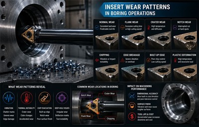
Insert wear rarely develops randomly.

In many boring operations, wear patterns become one of the earliest indicators that machining stability is beginning to deteriorate. Long before catastrophic edge failure appears, inserts often already show evidence of vibration amplification, thermal instability, chip evacuation restriction, or coolant inconsistency inside the bore.
Experienced machining engineers usually evaluate insert wear together with machine behavior rather than treating wear as an isolated tooling issue.
In real production environments, operators often notice:
- Spindle load oscillation
- Harmonic cutting sound
- Bore finish inconsistency
- Offset correction frequency increasing
- Chip evacuation becoming less stable
- Unpredictable tool life between production batches
before severe visible insert damage fully develops.
This is especially true in deep-hole and long-overhang boring where machining instability tends to accumulate progressively during continuous production.
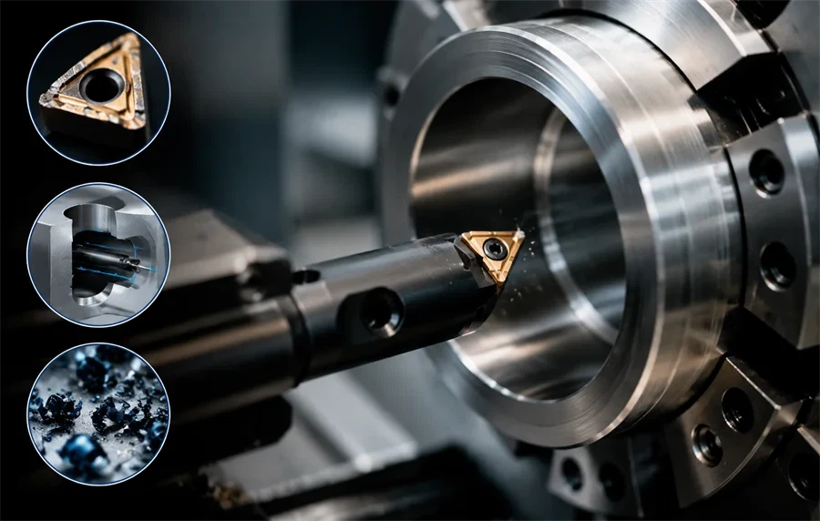
Why Boring Operations Create Faster Wear Acceleration
Compared with external turning, internal boring creates a more confined and less stable cutting environment.

Several instability factors often exist simultaneously:
- Long overhang conditions
- Reduced boring bar rigidity
- Limited coolant penetration depth
- Restricted chip evacuation volume
- Thermal concentration inside the bore
- Continuous vibration reflection along the boring bar
In small-diameter boring, rigidity decreases further while cutting force concentration remains relatively high. Coolant flow and chip evacuation also become more restricted as bore diameter decreases.
This combination makes insert wear progression less predictable than in external machining.
Why Wear Sometimes Accelerates Suddenly
In stable machining, wear progresses gradually.
In unstable boring operations, wear progression often follows a chain reaction:
- Cutting pressure increases
- Boring bar deflection grows
- Harmonic vibration develops
- Chip evacuation becomes less stable
- Heat concentration increases
- Edge rigidity weakens
- Wear accelerates rapidly
Once this cycle begins, process stability can deteriorate unexpectedly during long production runs.
Operators sometimes notice spindle load oscillating rhythmically rather than rising continuously once harmonic vibration begins developing inside the bore.
Flank Wear Often Reveals Boring Instability Earlier Than Chatter
Flank wear develops where the insert contacts the machined bore surface.

Under stable conditions, flank wear usually progresses relatively evenly. In unstable boring operations, however, vibration continuously changes the insert contact pressure against the bore wall.
What Operators Usually Observe First
In many production environments, operators notice machining instability before severe flank wear becomes visually obvious.
Common observations include:
- Bore finish changing between parts
- Light chatter marks appearing intermittently
- Spindle load variation during long cycles
- Insert indexing frequency increasing unexpectedly
- Surface finish gradually becoming matte or inconsistent
- Offset adjustments becoming more frequent during unattended machining
Inside deep bores, chip recutting often accelerates this process. Chips trapped near the cutting zone repeatedly contact the insert flank, increasing wear unpredictably.
What Flank Wear Usually Indicates
| Combined Symptoms | Likely Root Cause |
|---|---|
| Flank wear + chatter marks | Poor damping rigidity |
| Flank wear + spindle load oscillation | Chip recutting instability |
| Rapid wear during long-overhang boring | Excessive deflection |
| Uneven wear between production batches | Setup inconsistency |
| Fast wear despite moderate cutting speed | Coolant access limitation |
Many manufacturers initially assume insert grade problems. In practice, boring instability often contributes more heavily to flank wear progression than coating differences alone.
Why Flank Wear Progression Becomes Unstable
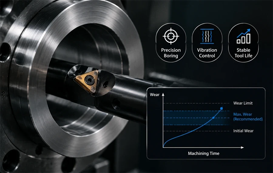
Flank wear rarely remains linear forever.
Once wear reaches a critical threshold:
- Cutting force rises sharply
- Heat concentration increases
- Deflection sensitivity grows
- Bore accuracy begins drifting
- Vibration amplification increases
At this stage, unattended machining reliability often declines rapidly.
In some production environments, the first several parts may remain stable while thermal expansion gradually accumulates inside the boring system. Once thermal growth changes the cutting condition, wear progression may accelerate suddenly.
Crater Wear Usually Signals Thermal Instability
Crater wear develops on the rake face where hot chips slide across the insert surface.
During continuous boring operations, chips can carry large amounts of concentrated heat directly across the rake face for extended periods.
Once coolant penetration becomes inconsistent deeper inside the bore, crater wear often accelerates rapidly.
What Operators Usually Notice
Before severe crater wear becomes visually obvious, operators often observe:
- Darker chip color
- Sharper harmonic cutting sound
- Increasing spindle load fluctuation
- Surface finish instability during long cuts
- Sudden edge failure after previously stable machining
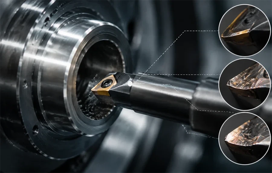
When inspected closely, the insert typically shows:
- A crater-shaped depression behind the cutting edge
- Thermal discoloration near the rake face
- Edge thinning near the chip contact zone
Why Deep-Hole Boring Accelerates Crater Wear
Inside deep bores, coolant behavior changes significantly:
- Coolant pressure weakens with depth
- Heat evacuation becomes less efficient
- Chip contact time increases
- Flow turbulence becomes less stable
- Coolant sometimes fails to reach the hottest cutting zones consistently
In high-volume production environments, operators may continue increasing cutting speed to maintain spindle utilization targets even after crater wear begins accelerating.
This often improves short-term throughput while reducing long-term machining consistency.
How Crater Wear Progression Often Develops
Crater wear commonly progresses through a thermal instability sequence:
- Rake face temperature rises
- Edge hardness decreases
- Cutting pressure becomes unstable
- Harmonic vibration increases
- Nose chipping begins
- Surface finish deteriorates rapidly
In long-overhang boring, this progression can accelerate quickly once edge rigidity falls below a stable threshold.
Nose Wear Often Indicates Vibration Concentration
The insert nose radius experiences concentrated thermal load, cutting pressure, and vibration stress simultaneously.
In small-diameter boring especially, the insert corner carries a disproportionately large percentage of the total cutting load because the cutting zone itself becomes highly confined.
Why Small-Diameter Boring Creates Earlier Nose Failure
Several machine behavior limitations combine together:
- Lower boring bar stiffness
- Reduced insert support area
- Restricted coolant delivery
- Limited chip evacuation volume
- Increased vibration sensitivity
- Higher thermal concentration near the cutting edge
Because of these constraints, nose wear progression often becomes less predictable than in larger-diameter boring applications.
What Operators Usually Observe
Common production symptoms include:
- Intermittent vibration marks
- Irregular feed mark patterns
- Bore finish inconsistency between cycles
- More manual operator intervention
- Unexpected corner chipping during stable parameter conditions
The insert itself often shows:
- Corner rounding
- Small fractures near the nose radius
- Uneven localized wear
- Edge breakdown near the corner transition zone
Why Lowering Feed Rate Doesn't Always Solve Nose Wear
Many operators reduce feed rate first once nose chipping appears.
This sometimes reduces immediate cutting force.
However, if harmonic vibration remains unchanged, instability often continues damaging the insert edge. Lower feed rates may reduce productivity while leaving the actual rigidity problem unresolved.
In many long-overhang applications, improving damping rigidity stabilizes insert life more effectively than reducing feed alone.
Boundary Wear Often Reveals Chip Evacuation and Thermal Distribution Problems
Boundary wear develops near the depth-of-cut line where thermal gradients and cutting stress become uneven.
This wear pattern becomes especially aggressive when machining materials that generate work-hardened surface layers.
What Operators Usually Observe
Boundary wear often creates inconsistent machining behavior:
- Groove marks appearing intermittently
- Localized finish deterioration
- Sudden edge chipping near the depth-of-cut zone
- Unstable tool life between production runs
- Instability increasing during interrupted chip flow
The insert usually develops:
- A localized groove near the cutting boundary
- Uneven edge wear concentration
- Stress damage near the transition zone
Why Deep-Hole Machining Accelerates Boundary Wear
Inside deep bores:
- Chip evacuation delay increases
- Chips repeatedly contact the cutting zone
- Coolant distribution changes with depth
- Thermal distribution becomes uneven
- Harmonic vibration amplifies near restricted flow zones
As chip packing begins near evacuation restriction points, boundary wear often accelerates rapidly.
The Wear Mechanisms Behind Accelerated Tool Failure
Most insert wear patterns involve multiple wear mechanisms simultaneously.
Understanding these mechanisms helps explain why wear progression sometimes becomes unstable unexpectedly.
Abrasive Wear
Abrasive wear develops when hard particles inside the workpiece scratch the insert surface.
This commonly occurs during machining of:
- Cast iron
- Forged materials
- Oxidized surfaces
- Components containing hard inclusions
In precision boring operations, abrasive wear may slowly reduce bore consistency before obvious edge failure appears.
Adhesive Wear
Adhesive wear occurs when workpiece material temporarily bonds to the insert surface under high pressure and temperature.
This commonly appears during:
- Low-speed heavy cutting
- Stainless steel machining
- Difficult alloy machining
- Poor lubrication conditions
Built-up edge often accompanies adhesive wear.
This may temporarily reduce crater wear by lowering temperature while simultaneously increasing tearing and surface instability from inconsistent built-up edge formation.
Diffusion Wear
At elevated temperatures approaching 800°C to 1000°C, chemical elements inside carbide inserts begin diffusing into the chip material.
As diffusion progresses:
- Edge hardness decreases
- Crater wear accelerates
- Brittleness increases
- Edge failure becomes less predictable
Diffusion wear becomes especially important during long-cycle continuous boring where thermal control becomes increasingly difficult over time.
Oxidation Wear
During intermittent boring with inconsistent coolant delivery, oxidation often develops around the hottest edge zones experiencing repeated thermal cycling.
The oxide layer becomes brittle and gradually breaks away during machining.
Oxidation wear commonly accelerates under:
Intermittent cutting
Inconsistent coolant delivery
Repeated thermal cycling
Dry high-temperature machining
In real production environments, oxidation wear rarely appears independently. It usually combines with flank wear or crater wear under unstable thermal conditions.
Why Insert Wear Problems Are Frequently Misdiagnosed
Many machining teams evaluate insert wear too narrowly.
Common assumptions include:
|
Common Assumption |
What Often Actually Happens |
|---|---|
| Poor insert quality | Boring instability |
| Incorrect insert grade | Excessive overhang |
| Coating failure | Built-up edge instability |
| Normal wear progression | Chip recutting inside the bore |
| Random tool life variation | Coolant inconsistency at depth |
| Feed rate too high | Harmonic vibration instability |
Operators often lower cutting speed first because it appears operationally safer.
However, reducing speed alone may:
- Lower thermal load
- Increase built-up edge formation
- Reduce productivity
- Leave vibration instability unresolved
In many deep-hole boring applications, improving damping rigidity and coolant consistency produces more stable long-term results than repeatedly changing insert grades.
Practical Ways to Improve Insert Life in Boring Operations
The correct solution depends on the actual instability source.
However, several improvements consistently stabilize boring performance:
- Reduce unnecessary overhang whenever geometry allows
- Improve damping rigidity
- Maintain coolant delivery deeper inside the bore
- Improve chip evacuation reliability
- Reduce chip packing near restricted zones
- Match insert geometry to the cutting condition
- Improve workholding rigidity
- Monitor wear progression before catastrophic failure develops
In many valve body machining and deep internal boring applications, overhang reduction may not be fully possible because of part geometry restrictions.
In these situations, improving damping behavior, coolant flow stability, thermal evacuation capability, and chip evacuation together often produces more stable long-term machining performance than aggressively lowering cutting parameters independently.
Final Thoughts
Insert wear patterns provide valuable information about machining dynamics inside the bore.
They often reveal:
- Harmonic vibration behavior
- Thermal instability
- Coolant delivery limitations
- Chip evacuation restriction
- Deflection sensitivity
- Machine rigidity limitations
In precision boring and deep-hole machining especially, improving insert life usually requires evaluating the interaction between:
- Overhang ratio
- Damping rigidity
- Coolant behavior
- Thermal stability
- Chip evacuation efficiency
- Machine capability
- Long-cycle process stability
rather than optimizing only a single variable independently.
Sijitonghui works with manufacturers to evaluate anti-vibration boring strategies, long-overhang stability conditions, coolant access limitations, and deep-hole machining reliability when improving process consistency in demanding internal boring applications.