Insert wear inside deep bores rarely behaves in a smooth or predictable way.
A setup that machines normally at 3×D overhang may suddenly become unstable at 6×D. Sometimes the spindle load still looks completely normal while insert wear starts accelerating unexpectedly.
That is one reason deep-hole boring problems are often misdiagnosed.
The insert itself usually is not the first thing failing.
In many unstable internal-turning operations, abnormal insert wear is a symptom of deeper instability involving:
- Dynamic rigidity loss
- Harmonic vibration
- Thermal concentration
- Chip recutting
- Damping limitations
- Insert-seat movement
- Bore deflection behavior
Some operations remain stable for several parts before wear suddenly collapses. Others chatter only during finishing passes even though roughing appears completely acceptable.
These problems are common in:
- Long-overhang boring
- Small-diameter internal turning
- Deep precision bores
- Hydraulic-component machining
- Mold-cavity boring
- Unattended production cycles
Understanding why insert wear changes dynamically during the cut is usually more important than simply changing insert grades repeatedly.
Why Deep Bores Change Insert Behavior
Deep internal turning changes the physical behavior of the entire machining system.
As overhang increases, the boring bar gradually loses dynamic stiffness. Small vibration movement near the insert tip becomes amplified deeper inside the bore.
Around 6×D overhang, many steel boring bars begin entering a much narrower stability window. By 8×D and beyond, even small changes in feed rate or spindle speed can shift the system into an unstable harmonic range.
At that stage:
- Chip formation becomes more sensitive
- Bore straightness becomes harder to maintain
- Heat evacuation becomes less predictable
- Surface finish may deteriorate suddenly
- Insert loading fluctuates continuously
The difficult part is that instability does not always appear immediately.
Some deep-bore operations remain stable during the first half of the cut before heat buildup, deflection, and vibration energy gradually accumulate enough to destabilize the insert edge deeper inside the bore.
Why Insert Wear Gets Misdiagnosed So Often
A common mistake in production environments is assuming abnormal insert wear automatically means the insert grade is wrong.
Sometimes the opposite correction makes the situation worse.
For example:
Harder grades may survive abrasion longer while becoming more vulnerable to sudden fracture
Larger nose radius may improve surface finish while increasing radial cutting force
Lower cutting speed may reduce crater wear while worsening built-up edge
Lower feed may improve edge survival while destabilizing chip breaking
Stronger edge preparation may improve edge security while increasing chatter sensitivity
In unstable deep-bore applications, these adjustments often shift the wear pattern rather than eliminate the instability itself.
Some machining teams continue changing inserts while the real problem comes from:
- Frequency overlap
- Regenerative chatter
- Poor damping behavior
- Insert-seat micro movement
- Coolant inconsistency
- Chip recutting inside the bore
The insert edge simply becomes the visible victim of a larger stability problem.
The Relationship Between Vibration and Insert Wear
Vibration changes how the insert contacts the material during cutting.
Instead of maintaining stable edge loading, the insert experiences repeated micro-impact cycles as harmonic movement changes cutting pressure continuously during spindle rotation.
The result is often:
- Irregular flank wear
- Micro-chipping
- Edge breakdown
- Thermal cracking
- Crater wear acceleration
- Bore taper drift
- Out-of-round bore behavior
Some operators notice that insert life remains stable for several cycles before collapsing rapidly once spindle speed enters a certain vibration-sensitive range.
This is often a sign of harmonic excitation rather than normal gradual wear progression.
The First Sign of Chatter Is Not Always Visible
In some unstable finishing passes, the earliest sign of chatter is not visible on the bore surface yet.
Operators often hear a slight change in cutting tone before measurable surface deterioration appears.
Sometimes the chips also change shape slightly before visible chatter marks develop.
This is one reason experienced machinists often detect instability earlier through sound and chip behavior rather than surface inspection alone.
Why Finishing Passes Sometimes Become Less Stable Than Roughing
Many operators expect finishing cuts to reduce insert stress because cutting forces are lower.
Deep internal turning often behaves differently.
During roughing, heavier cutting pressure sometimes suppresses smaller vibration movement temporarily. During finishing, lighter radial pressure may allow regenerative chatter to develop more freely.
This is why some bores:
- Rough normally
- Finish poorly
- Suddenly develop chatter marks
- Lose bore consistency near final passes
The problem is not always insufficient insert strength. Sometimes the system simply moved into a less stable dynamic condition.
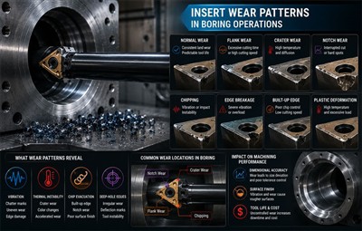
Flank Wear and Groove Wear
Controlled flank wear is normal during turning operations. Problems begin when wear progression becomes uneven or starts affecting bore geometry.

Groove wear near the depth-of-cut line becomes more aggressive when machining:
- Work-hardening materials
- Long continuous bores
- Interrupted internal surfaces
- Hardened outer layers
What Often Happens Inside Deep Bores
In some long-cycle boring operations, flank wear still appears visually moderate while bore quality has already drifted outside tolerance.
Operators sometimes continue using the insert because visible edge wear still looks acceptable. Meanwhile:
- Bore taper slowly increases
- Cylindricity deteriorates
- Surface finish becomes inconsistent
- Offset corrections become more frequent
The insert may not appear severely damaged yet, but the bore is already becoming unstable.
Practical Improvement Strategies
- Reduce excessive cutting speed gradually
- Improve coolant access near the insert nose
- Stabilize chip evacuation flow
- Reduce overhang where possible
- Improve damping capability
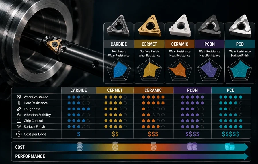
- Use wear-resistant grades when thermal load remains high
Inside smaller bores, chips sometimes stop evacuating smoothly near the rear side of the insert before suddenly releasing in clusters. That repeated chip hammering can accelerate groove wear surprisingly fast.
Crater Wear and Thermal Concentration
Crater wear develops on the rake face because of thermal concentration and diffusion wear.
This becomes more severe during:
- Long internal passes
- High-speed boring
- Heat-resistant alloy machining
- Restricted coolant environments

In deep bores, heat often remains trapped near the chip-flow zone longer than many operators expect.
The insert may still look acceptable externally while the rake face has already weakened enough to destabilize chip flow behavior.
Why Lower Speed Does Not Always Solve Crater Wear
Lower cutting speed can reduce thermal load temporarily. Excessive reduction sometimes creates additional instability instead:
- Chip curl becomes less predictable
- Built-up edge increases
- Chip evacuation weakens
- Chip packing risk rises deeper inside the bore
Some operations stabilize crater wear briefly while quietly increasing chip recutting inside the cavity.
That secondary chip impact can eventually become more damaging than the original crater wear itself.
Practical Improvement Strategies
- Use Al₂O₃-coated grades
- Improve heat evacuation through stable chip flow
- Use positive rake geometries where rigidity allows
- Reduce speed gradually instead of aggressively
- Improve coolant consistency near the cutting zone
Built-Up Edge and Adhesion Wear
Built-up edge forms when workpiece material welds temporarily onto the insert edge.
This becomes less predictable inside smaller bores because restricted chip space keeps chips close to the insert longer before evacuation.
Common Symptoms
- Random surface marks
- Sudden edge chipping
- Bore-finish inconsistency
- Irregular chip flow
- Dimensional instability
Some operators repeatedly lower cutting speed after edge chipping appears, unintentionally worsening adhesion behavior further.
Practical Improvement Strategies
- Increase cutting speed moderately
- Improve chip-flow consistency
- Use positive rake geometries
- Reduce unstable cutting interruptions
Plastic Deformation and Edge Collapse
Plastic deformation occurs when thermal and mechanical loading exceed the insert's ability to maintain edge shape.
This becomes increasingly aggressive in long-overhang boring because radial deflection continuously changes edge loading conditions during cutting.
Common Symptoms
- Edge deformation
- Bore-size instability
- Poor chip control
- Sudden edge collapse
- Surface-finish deterioration
Why Rigidity Eventually Becomes the Main Limitation
In many applications above 6×D to 8×D overhang, boring-system stability starts affecting insert survival more directly than small parameter changes.
At that stage:
- Lower feed alone rarely stabilizes wear
- Harder grades may worsen chatter
- Larger nose radius may increase radial force
- Stronger geometries may amplify vibration energy
The limitation gradually shifts from insert capability to damping behavior inside the boring system itself.
Thermal Cracking During Interrupted Cutting
Thermal cracks usually form perpendicular to the cutting edge because of repeated thermal cycling.
This commonly occurs during:
- Interrupted internal surfaces
- Inconsistent coolant flooding
- Repeated thermal shock
- Unstable temperature fluctuation
Small thermal cracks often spread slowly before catastrophic failure becomes visible.
In unattended machining environments, this creates serious scrap risk because insert failure may appear suddenly without obvious warning signs.
Flood Coolant Is Not Always Safer
Many production teams assume heavier coolant application automatically improves insert life.
In interrupted boring operations, unstable coolant flooding can repeatedly shock the insert edge thermally and worsen crack formation.
In some applications, controlled dry machining actually performs more consistently than unstable coolant delivery.
Practical Improvement Strategies
- Maintain consistent coolant delivery
- Reduce excessive thermal cycling
- Use tougher grades with stronger thermal-crack resistance
- Avoid unstable coolant interruption
Insert Fracture and Catastrophic Failure
Insert fracture usually indicates the cutting system exceeded its stable operating range.
This becomes especially aggressive during:
- Deep-hole boring
- Interrupted cuts
- Long-overhang turning
- Heavy roughing
- Poorly supported setups
Common Causes
- Excessive overhang
- Harmonic instability
- Weak insert geometry
- Large depth of cut
- Insert-seat movement
- Poor damping behavior
In some setups, the insert is not actually seated perfectly flat because chips or debris become trapped underneath during indexing. Even slight seating instability can amplify vibration behavior during long-overhang boring.
Practical Improvement Strategies
- Avoid unstable spindle-speed ranges
- Improve damping capability
- Reduce excessive overhang
- Improve insert-seat support stability
- Use tougher grades where impact loading remains high
Why Chip Evacuation Controls Tool Life
Chip evacuation is not only a productivity issue. In deep boring operations, it directly affects insert survival.
Poor chip evacuation increases:
- Thermal concentration
- Edge impact loading
- Chip recutting
- Bore-finish instability
- Surface damage
- Vibration sensitivity
In some smaller bores, chips begin recirculating intermittently before operators notice obvious chip packing.
Insert wear often accelerates rapidly during this stage.
Sometimes the bore sounds stable while chips are already striking the insert repeatedly deeper inside the cavity.
When Anti-Vibration Boring Systems Become Necessary
Standard steel boring bars perform adequately within shorter overhang ranges.
As overhang increases, vibration energy eventually exceeds what conventional steel bars can dissipate effectively.
At that stage, insert optimization alone usually stops producing stable long-term improvement.
The physical limitation is no longer primarily insert grade. It becomes the boring system's ability to absorb and suppress vibration energy before harmonic instability develops.
This becomes especially important when machining:
- Hydraulic components
- Valve bodies
- Mold cavities
- Precision automotive bores
- Small-diameter internal features
Stable damping systems improve:
- Bore straightness consistency
- Surface finish stability
- Tool life predictability
- Chip evacuation reliability
- Unattended machining confidence
Sijitonghui anti-vibration boring systems are designed for internal-turning environments where conventional boring setups struggle to maintain stability under long-overhang or deep-hole conditions.
Rather than relying entirely on conservative parameters, improved damping capability helps stabilize the machining process itself.
Practical Recommendations for Improving Insert Life
Evaluate the Entire Boring System
Before changing insert grades repeatedly, evaluate:
- Overhang ratio
- Dynamic rigidity
- Spindle condition
- Insert-seat stability
- Coolant direction
- Chip evacuation path
- Workholding rigidity
In many unstable deep-bore applications, these factors influence insert life more directly than insert grade selection.
Match Insert Geometry to Actual Cutting Behavior
Sharper geometries reduce cutting force but weaken edge strength.
Stronger geometries improve edge security while increasing vibration sensitivity in unstable setups.
The correct balance depends on:
- Bore depth
- Material behavior
- Harmonic stability
- Interrupted cutting severity
- Surface-finish requirements
Watch for Early Instability Signals
Many deep-bore problems begin appearing before catastrophic insert failure occurs.
Monitor for:
- Sudden bore-finish deterioration
- Changing cutting sound
- Random edge chipping
- Bore taper growth
- Irregular chip behavior
- Increasing chatter frequency during finishing passes
These signals often indicate growing instability before visible insert failure becomes severe.
FAQ
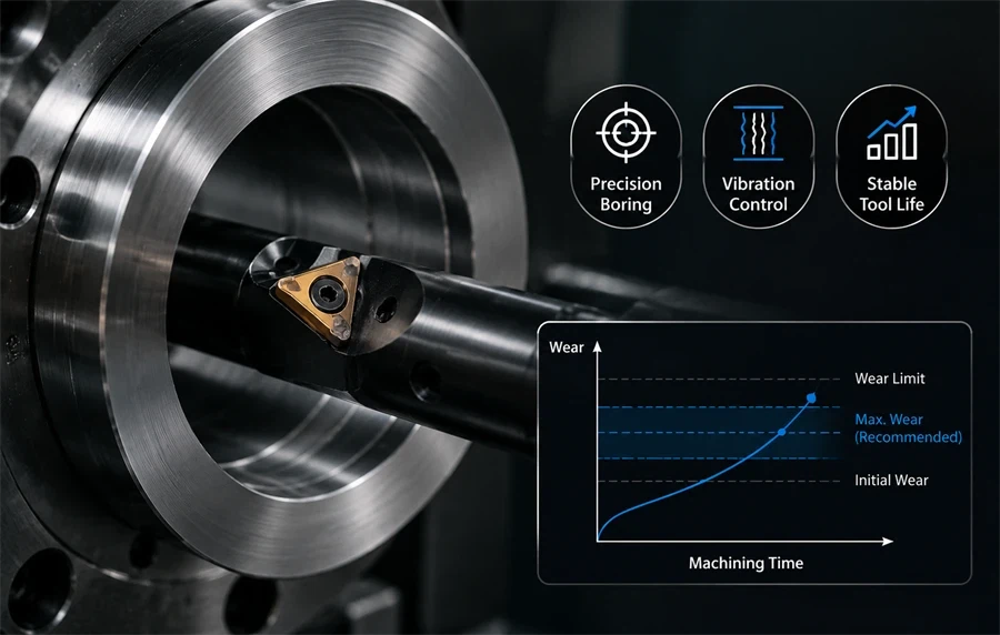
Why does insert wear suddenly increase near the end of a deep bore?
Heat buildup, radial deflection, and vibration energy often accumulate gradually deeper inside long bores. Insert loading may remain relatively stable early in the cut before becoming increasingly unstable near the end of the internal pass.
Can excessive coolant create thermal cracking?
Yes. Inconsistent coolant flooding can repeatedly shock the insert edge thermally, especially during interrupted cutting. In some applications, unstable coolant delivery creates more thermal-cracking risk than controlled dry machining.
Why does chatter sometimes appear only during finishing passes?
Finishing cuts reduce radial cutting pressure, which can allow regenerative chatter to develop more freely. Roughing sometimes suppresses smaller vibration movement that later becomes unstable during lighter finishing passes.
Why does insert wear look normal while bore finish gets worse?
Insert wear inside deep bores does not always appear severe visually during early instability stages. Bore taper, surface finish deterioration, and cylindricity drift may begin before obvious edge failure becomes visible.
Can chip recutting damage inserts even without obvious chip packing?
Yes. Chips may begin recirculating intermittently inside smaller bores before visible packing becomes obvious. Repeated chip impact can accelerate crater wear, groove wear, and edge chipping surprisingly quickly.
Final Thoughts
Insert wear inside deep bores is rarely an isolated insert problem.
In many unstable internal-turning operations, abnormal wear patterns reflect broader instability involving:
- Harmonic vibration
- Dynamic rigidity loss
- Thermal concentration
- Chip evacuation behavior
- Damping limitations
- Insert-seat movement
- Regenerative chatter
The most effective long-term improvement usually comes from understanding not only what wear pattern exists, but why the machining system is creating it dynamically throughout the cut.
For deep-hole boring and long-overhang internal turning, improving damping behavior and machining stability often delivers more consistent results than repeated insert changes alone.
If your operation is struggling with unstable bore quality, vibration-related insert wear, or long-overhang machining limitations, Sijitonghui can help evaluate a more stable boring solution based on your actual machining environment.